This topic describes the parameters of the RF Output block.
|
Tab |
N5186A N5185A |
|---|---|
| This link opens a separate topic. | |
| This link opens a separate topic. | |
| List/Step Sweep | This link opens a separate topic. |
|
Frequency Center (Remote command only) |

For multi-channel capability only.
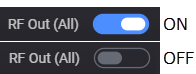
Turns the RF outputs on or off for all the channels in the instrument. This is a master control that gates the individual states. If this control is off, no RF power is emitted from any of the channels; however, the individual channels retain the state of their setting. If this control is on, the RF outputs are on if their individual state is on. To enable or disable individual channels see RF Out.
|
GUI Location |
RF Out (All) |
|
SCPI Command |
[:SOURce]:RFALl:OUTPut[:STATe] ON|OFF|1|0 [:SOURce]:RFALl:OUTPut[:STATe]? |
|
SCPI Example |
RFAL:OUTP OFF RFAL:OUTP? |
|
Preset |
ON |
|
State Saved |
Yes |
|
Choices |
OFF | ON |
Enables or disables the RF output of the indicated channel. To enable or disable all channels, see RF Out (All).
The state of RF Out (All) does not change the RF Out state of a specific channel. For example, if RF Out for Channel 1 is set to on and RF Out (All) is set to off, no power is emitted from the RF Output connector of Channel 1. Likewise, if RF Out for Channel 1 is set to off and RF Out (All) is set to on, no power is emitted from the RF Output connector of Channel 1.
|
GUI Location |
RF Out |
|
SCPI Command |
[:SOURce][:RF<channel>]:OUTPut[:STATe] ON|OFF|1|0 [:SOURce][:RF<channel>]:OUTPut[:STATe]? |
|
SCPI Example |
OUTP ON OUTP? |
|
Preset |
OFF |
|
State Saved |
Yes |
|
Choices |
OFF | ON |
Remote command only.
Sets the power mode of the indicated channel.
Fixed: RF output power is controlled by Power (Total RMS).
List : RF output power is controlled by List/Step Sweep settings.
|
SCPI Command |
[:SOURce][:RF<channel>]:POWer:MODE FIXed|LIST [:SOURce][:RF<channel>]:POWer:MODE? |
|
SCPI Example |
POW:MODE LIST POW:MODE? |
| Couplings |
|
|
Preset |
FIX |
|
State Saved |
Yes |
| Choices | Fixed | List |
| Backward Compatibility SCPI |
N5182B: [:SOURce]:POWer:MODE
|
| Backwards Compatibility Notes |
For N51xxB: Alias [:SOURce]:POWer:MODE SWEep to [:SOURce]:RF1:POWer :MODE LIST Alias [:SOURce][:RF<channel>]:POWer:MODE SWEep to [:SOURce][:RF<channel>]:POWer :MODE LIST |
Controls the RF output power of the indicated channel.
This is the value that the instrument attempts to output. The actual value might be different from the specified value due to the hardware limitations. For example, the output power is different when a high power value is specified with Attenuation Auto off (that is, Attenuation Hold on).
When Power Sweep State is ON, changing the power sets the Power Sweep State to OFF.
|
GUI Location |
RF Output > Amplitude tab > Power (Total RMS) |
|
SCPI Command |
[:SOURce][:RF<channel>]:POWer[:LEVel][:IMMediate][:AMPLitude] <ampl> [:SOURce][:RF<channel>]:POWer[:LEVel][:IMMediate][:AMPLitude]? |
|
SCPI Example |
POW -50 POW? |
|
Notes |
The maximum value of this setting is a settable maximum and the datasheet describes actual specified max power that the instruments are capable of. |
|
Dependencies |
When the power is clipped to the User Power Limit the error message "Clipped to User Power Limit" is displayed on the GUI or -222; "Data out of range; Clipped to User Power Limit" to SCPI. |
|
Preset |
-100 dBm |
|
State Saved |
Yes |
|
Min |
For |
|
Max |
For
|
|
Resolution |
0.01 dBm |
Power List / Step Sweep
Refer to the sections Power Start and Power Stop in Step Sweep Configuration.
Remote command only.
Sets the instrument’s power with the maximum throughput. As the purpose of this command is for speed, there is no limit checking, no coupling, and no update of the value on the front panel. When using this command, there is no inclusion of amplitude offset or amplitude reference. The value is a floating point number in dBm. No error message is raised if the value is clipped.
|
SCPI Command |
FAST<channel>:POWer <double> |
|
SCPI Example |
FAST:POW -50 |
|
Notes |
This command performs no coupling, does not support UP, DOWN, MIN, MAX, DEF. The value is floating point value in dBm; no DB or DBM units are allowed. |
|
State Saved |
No |
|
Min |
For -135.0 |
|
Max |
For 20 dBm in all frequencies not covered by the options:
|
|
Resolution |
0.01 |
Remote command only.
Sets the instrument’s frequency and power with the maximum throughput. As the purpose of this command is for speed, there is no limit checking, no coupling, and no update of the value on the front panel. When using this command, there is no inclusion of frequency offset, multiplier, frequency reference, amplitude offset, or amplitude reference. The value is an integer frequency in 10 uHz resolution. No error message is raised if the value is clipped.
|
SCPI Command |
FAST<channel>:FP <integer>,<double> |
|
SCPI Example |
FAST:FP 300000000000000,-50 |
|
Notes |
This command performs no coupling, does not support UP, DOWN, MIN, MAX, DEF. The frequency value is an integer in 10 uHz, power value is a double in dBm; no HZ, KHZ, MHZ, GHZ, DB, DBM units are allowed. See Fast Frequency section for details of the frequency setting and Fast Powersection for details of the power setting. |
|
State Saved |
No |
Displays or returns the peak envelope power.
|
GUI Location |
RF Output > Amplitude tab > Peak Envelope Power |
|
SCPI Command |
[:SOURce][:RF<channel>]:POWer:PEPower? |
|
SCPI Example |
POW:PEP? |
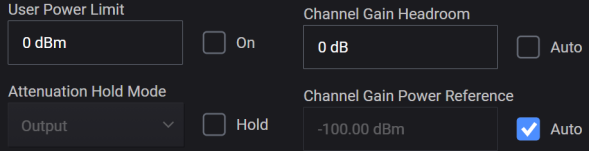
Enables the maximum output power limit set by User Power Limit of the indicated channel.
The value set with this command is not affected by *RST or a power cycle. It is reset to default value with Restore System Defaults.
|
GUI Location |
RF Output > Amplitude tab > User Power Limit |
|
SCPI Command |
[:SOURce][:RF<channel>]:POWer:USER:ENABle ON|OFF|1|0 [:SOURce][:RF<channel>]:POWer:USER:ENABle? |
|
SCPI Example |
POW:USER:ENAB ON POW:USER:ENAB? |
|
Dependencies |
Default value of OFF is set by Restore System Defaults |
|
Preset |
OFF |
|
State Saved |
Persistent, survives preset and power cycle but not saved in the instrument state. |
Sets the maximum output power level for the indicated channel that is lower than the instrument’s normal maximum output power. This affects all modes of power operation. This affects the Amplitude value, but features such as AM may allow the power to exceed the Amplitude value. In other words, this is not a hardware power clamp.
The value is not affected by recall, *RST, Preset or a power-cycle. It is reset to the default value with Restore System Defaults.
|
GUI Location |
RF Output > Amplitude tab > User Power Limit |
|
SCPI Command |
[:SOURce][:RF<channel>]:POWer:USER:MAXimum <ampl> [:SOURce][:RF<channel>]:POWer:USER:MAXimum? |
|
SCPI Example |
POW:USER:MAX 10 POW:USER:MAX? |
|
Dependencies |
Default value of 0 dBm is set by Restore System Defaults |
|
Preset |
0 dBm |
|
State Saved |
No |
|
Min |
For |
|
Max |
For N5185A and N5186A: 20 dBm in all frequencies not covered by the options:
|
|
Resolution |
0.01 dBm |
Enabling attenuation hold (Hold checkbox is marked in the GUI) turns off automatic attenuation and allows you to select one of the following possible RF Output behaviors in the Attenuation Hold Mode drop-down menu.
|
Attenuation Hold Mode |
Description |
Summary |
|---|---|---|
|
Output |
Holds only the output attenuators but allows non-output attenuators to change. Output attenuators are defined as those that, when changed, affect the source match and have the potential to introduce some discontinuity on power changes when not held. They are also distinct in that they are selected based on mode, requested power and frequency only and have no dependency on signal level coming from the DAC. Changing non-output attenuation can result in small discontinuities. |
|
|
All |
Holds all attenuators, avoiding all attenuation-based discontinuities at the cost of dynamic range. |
|
|
GUI Location |
RF Output > Amplitude tab > Attenuation Hold Mode |
|
SCPI Command |
[:SOURce][:RF<channel>]:POWer:ATTenuation:HOLD:MODE OUTPut [:SOURce][:RF<channel>]:POWer:ATTenuation:HOLD:MODE? |
|
SCPI Example |
POW:ATT:HOLD:MODE ALL POW:ATT:HOLD:MODE? |
|
Preset |
OUTPut |
|
Range |
Output|All |
|
State Saved |
Y |
Turns the output Attenuator Hold function off or on. When Hold is off (checkbox cleared), auto attenuation is on; when Hold is on, auto attenuation is off. The GUI enables or disables the Hold function, while the SCPI command enables or disables the Auto function. In other words, the GUI and SCPI selections achieve the same result with opposite settings, as outlined in the table below.
|
GUI |
SCPI |
Description |
|---|---|---|
|
|
POW:ATT:AUTO ON |
The attenuator setting is automatically changed as needed to maintain the RF output power level.
|
|
|
POW:ATT:AUTO OFF |
The attenuator remains at its current setting.
|
You can use the Attenuation Hold function to eliminate power level transients that can occur with attenuator switching.
When Attenuation Hold is turned on with User Power Limit on, the output power may exceed the specified power limit because the specified attenuation may not be high enough to achieve the power limit.
|
GUI Location |
RF Output > Amplitude tab > Attenuation [or Attenuation Hold Mode] > Hold |
|
SCPI Command |
[:SOURce][:RF<channel>]:POWer:ATTenuation:AUTO ON|OFF|1|0 [:SOURce][:RF<channel>]:POWer:ATTenuation:AUTO? |
|
SCPI Example |
POW:ATT:AUTO OFF POW:ATT:AUTO? |
| Notes |
For Attenuation Auto is On and is not changeable (however, sending the SCPI command does not generate an error.) |
|
Preset (SCPI) |
ON (Attenuation Auto) |
|
Preset (GUI) |
OFF (Attenuation Hold) |
|
State Saved |
Yes |
|
Choices |
OFF | ON |
For
Click the ![]() icon displayed with the Perform Spot Correction button to see the allowed frequencies and power levels for which spot correction is available on your instrument. The allowed frequencies and power levels for spot correction is based on the firmware with which your instrument is calibrated. Refer to Notes row below for details.
icon displayed with the Perform Spot Correction button to see the allowed frequencies and power levels for which spot correction is available on your instrument. The allowed frequencies and power levels for spot correction is based on the firmware with which your instrument is calibrated. Refer to Notes row below for details.
|
GUI Location |
RF Output > Amplitude tab > Perform Spot Correction |
|
SCPI Command |
[:SOURce][:RF<channel>]:POWer:SCORrection |
|
SCPI Example |
POW:SCOR |
|
State Saved |
No |
| Notes |
Spot correction is available within particular frequency and amplitude ranges. For instruments calibrated with A.13.xx firmware, the ranges are:
For instruments calibrated with A.14.xx or above firmware, the ranges are:
|
|
Modified S/W Revision |
A.14.00, Updated ranges of frequency based on calibration. |
Requires Option V08.
The spot correction provides capability to perform the correction for termination to an ideal 50 ohm load or to your measurement setup impedance match (incident to current load).
|
GUI Location |
RF Output > Amplitude tab > Spot Correction Termination |
|
SCPI Command |
[:SOURce][:RF<channel>]:POWer:SCORrection:TERMination NORMal|CLOad [:SOURce][:RF<channel>]:POWer:SCORrection:TERMination? |
|
SCPI Example |
POW:SCOR:TERM CLO POW:SCOR:TERM? |
|
Preset |
NORM |
|
State Saved |
Yes |
The Channel Gain is the instrument’s digital and analog setup to achieve a particular power with an input, such as a waveform. There are two settings for the Channel Gain: Power Headroom and Power Reference. See Figure: Determining Instrument’s Channel Gain Setup. When Channel Gain Power Headroom Auto is on, the Channel Gain Power Headroom is automatically set to the crest factor (after runtime scaling) of the waveform(s) being played. When Channel Gain Power Reference Auto is on, the Channel Gain Power Reference is the RF Power.
Adjusting the power headroom or power reference allows for selecting a particular setup across a range of powers or for optimizations when the instrument does not know the best optimization point. These settings accomplish the same function as Attenuator Hold in other Keysight Technologies signal generators.
The channel gain power headroom must be at or above the total crest factor of all combined signals, including AWGN and CW interferers, to avoid a DAC overflow. When Auto is on, the system will set this value to the combined crest factors (after runtime scaling). The larger this value is, the less likely that summed signals will run out of power or have an arithmetic overflow, but less dynamic range will be available.
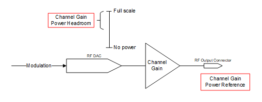
Figure: Determining Instrument’s Channel Gain Setup
See Figure: Power Gain vs Signal Power to understand how a particular signal’s power relates to the static instrument setup set by the channel gain power settings. The headroom sets the amount of digital back-off from full-scale CW. The channel gain reference power Pref sets the optimized gain. These two values determine the maximum peak power. Digital Scale is the dynamic power control applied in the instrument’s DSP to get the appropriate power given the requested power of the signal to play and its crest factors. The crest factors are determined implicitly for internally generated waveforms, or explicitly using the rms of the waveform(s).
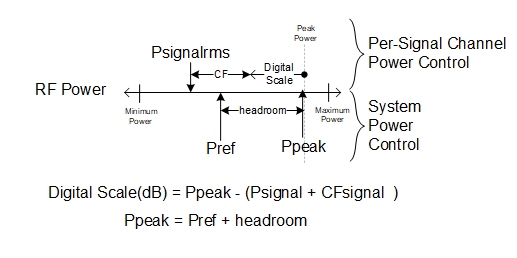
Figure: Power Gain vs Signal Power
The reference headroom sets the amount of digital back-off from full-scale CW. This value must be at or above the total crest factor of all combined signals to avoid overflow. The larger this value is, the less likely that summed signals will run out of power or have an arithmetic overflow, but less dynamic range will be available. See Channel Gain Overview.
|
GUI Location |
RF Output > Amplitude tab > Channel Gain Headroom |
|
SCPI Command |
[:SOURce][:RF<channel>]:POWer:CGAin:HEADroom <rel_ampl> [:SOURce][:RF<channel>]:POWer:CGAin:HEADroom? |
|
SCPI Example |
POW:CGA:HEAD 10DB POW:CGA:HEAD? |
|
Notes |
For values larger than 20 dB, the system may not be capable of delivering maximum specified power. |
|
Dependencies |
When this value is set, Channel Gain Power Headroom Auto is set to off. |
|
Preset |
0 dB |
|
State Saved |
Y |
|
Min |
0 dB |
|
Max |
100 dB |
|
Resolution |
0.01 dB |
When in auto mode, the Power Headroom is the crest factor of the waveform(s) being played, if known. When in CW mode (no modulation), the headroom is 0 dB. See Channel Gain Overview.
|
GUI Location |
RF Output > Amplitude tab > Channel Gain Headroom Auto |
|
SCPI Command |
[:SOURce][:RF<channel>]:POWer:CGAin:HEADroom:AUTO ON|OFF|1|0 [:SOURce][:RF<channel>]:POWer:CGAin:HEADroom:AUTO? |
|
SCPI Example |
POW:CGA:HEAD:AUTO ON POW:CGA:HEAD:AUTO? |
|
Notes |
When this feature is turned off, the automatic values are retained. |
|
Preset |
ON |
|
State Saved |
Y |
This value is the optimized power level for purposes of power control. This follows RF Power when Auto is on. See Channel Gain Overview.
|
GUI Location |
RF Output > Amplitude tab > Channel Gain Power Reference |
|
SCPI Command |
[:SOURce][:RF<channel>]:POWer:CGAin:REFerence <ampl> [:SOURce][:RF<channel>]:POWer:CGAin:REFerence? |
|
SCPI Example |
POW:CGA:REF 0DBM POW:CGA:REF? |
|
Notes |
The maximum value of this setting is a settable maximum and the datasheet describes actual specified max power that the instruments are capable of. |
|
Dependencies |
When the power is clipped to the User Power Limit the error message "Clipped to User Power Limit" is displayed on the GUI or -222;"Data out of range;Clipped to User Power Limit" to SCPI. When this value is set, Channel Gain Power Reference Auto is set to off. |
|
Preset |
-100 dBm |
|
State Saved |
Y |
|
Min |
-135 dBm |
|
Max |
For With Option 1EA: 30 dBm |
|
Resolution |
0.01 dBm |
When in auto mode, the Power Reference is the RF Power. See Channel Gain Overview.
|
GUI Location |
RF Output > Amplitude tab > Channel Gain Power Reference Auto |
|
SCPI Command |
[:SOURce][:RF<channel>]:POWer:CGAin:REFerence:AUTO ON|OFF|1|0 [:SOURce][:RF<channel>]:POWer:CGAin:REFerence:AUTO? |
|
SCPI Example |
POW:CGA:REF:AUTO ON POW:CGA:REF:AUTO? |
|
Notes |
When this feature is turned off, the automatic values are retained. This value cannot be set to on when Attenuation Auto is off (that is, Attenuation Hold is on). |
|
Preset |
ON |
|
State Saved |
Y |
Provides a power offset (in dB) to the actual RF output of the indicated channel. This simulates a power level at a test point beyond the RF OUTPUT connector without changing the actual RF output power. The offset value only affects the displayed amplitude setting. You can enter an offset at any time in either normal operation or amplitude reference mode.
|
GUI Location |
RF Output > Amplitude tab > Amplitude Offset |
|
SCPI Command |
[:SOURce][:RF<channel>]:POWer[:LEVel][:IMMediate]:OFFSet <rel_ampl> [:SOURce][:RF<channel>]:POWer[:LEVel][:IMMediate]:OFFSet? [MAXimum|MINimum] |
|
SCPI Example |
POW:OFFS 10 dB POW:OFFS? |
|
Preset |
0 dB |
|
State Saved |
Yes |
|
Range |
-200 to 200 dB |
|
Resolution |
0.01 dB |
Enables or disables the amplitude reference mode for the indicated channel. When the amplitude reference mode is on, subsequent amplitude parameters are set relative to the reference value.
|
GUI Location |
RF Output > Amplitude tab > Amplitude Reference |
|
SCPI Command |
[:SOURce][:RF<channel>]:POWer:REFerence:STATe ON|OFF|1|0 [:SOURce][:RF<channel>]:POWer:REFerence:STATe? |
|
SCPI Example |
POW:REF:STAT ON POW:REF:STAT? |
|
Preset |
OFF |
|
State Saved |
Yes |
|
Choices |
OFF | ON |
Provides an amplitude reference value for the indicated channel.
|
GUI Location |
RF Output > Amplitude tab > Amplitude Reference |
|
SCPI Command |
[:SOURce][:RF<channel>]:POWer:REFerence <ampl> [:SOURce][:RF<channel>]:POWer:REFerence? [MAXimum|MINimum] |
|
SCPI Example |
POW:REF -20 POW:REF? |
|
Preset |
0 dBm |
|
State Saved |
Yes |
|
Range |
-330 to 220 dBm |
|
Resolution |
0.01 dBm |
This immediate action sets the current output amplitude, along with any offset, as a 0 dBm reference value to the indicated channel.
|
GUI Location |
RF Output > Amplitude tab > Set Reference to Current Amplitude |
|
SCPI Command |
[:SOURce][:RF<channel>]:POWer:REFerence:SET |
|
SCPI Example |
POW:REF:SET |
Tap or click within this area of the GUI to access the Frequency and Amplitude Adjustment Setup screen, where you can configure these parameters. Once you complete your configuration, click or tap Back and this area updates to reflect your custom configuration.
Remote command only.
Sets the frequency mode of the indicated channel.
CW: RF Output frequency is fixed to Frequency (CW).
LIST: RF Output frequency is controlled by List / Step Sweep settings.
|
SCPI Command |
[:SOURce][:RF<channel>]:FREQuency:MODE CW|LIST [:SOURce][:RF<channel>]:FREQuency:MODE? |
|
SCPI Example |
FREQ:MODE CW FREQ:MODE? |
| Couplings |
|
|
Preset |
CW |
|
State Saved |
Yes |
|
Choices |
CW|List |
| Backwards Compatibility SCPI |
N51xxB: [:SOURce]:FREQuency:MODE |
| Backwards Compatibility Notes |
For N51xxB: Alias [:SOURce]:FREQuency:MODE FIXed to [:SOURce]:RF1:FREQuency:MODE CW Alias [:SOURce]: FREQuency:MODE SWEep to [:SOURce]:RF1:FREQuency:MODE LIST Alias [:SOURce][:RF<channel>]:FREQuency:MODE FIXed to [:SOURce][:RF<channel>]:FREQuency:MODE CW Alias [:SOURce][:RF<channel>]:FREQuency:MODE SWEep to [:SOURce][:RF<channel>]:FREQuency:MODE LIST |
Controls the output frequency of the indicated channel.
When Vector Modulation is on, this is the center of the modulation frequency.
When Frequency List/Step Sweep is on, changing the frequency sets the Frequency List/Step Sweep off.
|
GUI Location |
RF Output > Frequency and Phase tab > Frequency (CW) |
|
SCPI Command |
[:SOURce][:RF<channel>]:FREQuency[:CW] <freq> [:SOURce][:RF<channel>]:FREQuency[:CW]? |
|
SCPI Example |
FREQ 3 GHZ FREQ? |
|
Preset |
1 GHz |
|
State Saved |
Yes |
|
Min |
For N5186A and N5185A= 9 kHz |
|
Max |
For With Option 503 = 3 GHz With Option 506 = 6 GHz With Option 508 = 8.5 GHz |
|
Resolution |
For N5185A / N5186A: 0.00001 Hz |
|
Backwards Compatibility SCPI |
N51xxB: [:SOURce]:FREQuency:FIXed |
|
Backwards Compatibility Notes |
For N51xxB: Alias [:SOURce]:FREQuency:FIXed to [:SOURce]:RF1:FREQuency[:CW] Alias [:SOURce][:RF<channel>]:FREQuency:FIXed to [:SOURce][:RF<channel>]:FREQuency[:CW] |
Remote command only.
Controls the incremental step value of the indicated channel for the Frequency CW or Fixed parameters. The value set with this command is not affected by *RST or a power cycle. It is reset to the default value with Restore System Defaults.
|
SCPI Command |
[:SOURce][:RF<channel>]:FREQuency[:CW]:STEP[:INCRement] <freq> [:SOURce][:RF<channel>]:FREQuency[:CW]:STEP[:INCRement]? [MAXimum|MINimum] |
|
SCPI Example |
FREQ:STEP 100 MHZ FREQ:STEP? |
|
Dependencies |
Default value of 100 kHz is set by Restore System Defaults |
|
Preset |
Not changed by Preset |
|
State Saved |
No |
|
Min |
For |
|
Max |
99 GHz |
|
Range |
0.01 Hz to 99 GHz |
|
Resolution |
For |
Remote command only.
Sets the instrument’s frequency with the maximum throughput. As the purpose of this command is for speed, there is no limit checking, no coupling, and no update of the value on the front panel. When using this command, there is no inclusion of frequency offset, multiplier, or frequency reference. The value is an integer frequency in 10 uHz resolution. No error message is raised if the value is clipped.
|
SCPI Command |
FAST<channel>:FREQuency <integer> |
|
SCPI Example |
FAST:FREQ 300000000000000 |
|
Notes |
This command performs no coupling, does not support UP, DOWN, MIN, MAX, DEF. The value is an integer in 10 uHz; no HZ, KHZ, MHZ, GHZ units are allowed. |
|
State Saved |
No |
|
Min |
For |
|
Max |
For
|
|
Resolution |
10 uHz |
Requires Option PCH.
This control selects the behavior of the phase across frequency changes.
Transition Mode of Continuous attempts to minimize spectral splatter on frequency transitions by maintaining the same phase across the point of the switch.
Transition Mode of Coherent causes the instrument to act as if all frequencies were generated by independent transmitters that are pulsed on and off; resulting in the phase of any given frequency will always reflect the same phase ramp over time, even if the source has changed to other frequencies in between.
Undefined means that the phase transition has no guaranteed phase behavior.
Reset will reset the phase to the Phase Offset on any frequency change.
|
GUI Location |
RF Output > Frequency and Phase tab > Phase Transition Mode |
|
SCPI Command |
[:SOURce][:RF<channel>]:PHASe:MODE CONTinuous|COHerent|UNDefined|RESet|MCOHerent [:SOURce][:RF<channel>]:PHASe:MODE? |
|
SCPI Example |
PHAS:MODE CONT PHAS:MODE? |
|
Notes |
For N5185A/N5186A without Option PCH, the value is Continuous and not changeable. Error message raised if user attempts to set value to HW that doesn’t provide it. For N5185A/N5186A with Option PCH, the default is Coherent. |
|
Preset |
For N5185A/N5186A with Option PCH: Coherent For N5185A/N5186A without Option PCH: Continuous |
|
State Saved |
Yes |
Controls the phase offset of the indicated channel.
With Option PCH, this parameter allows you to set the relative phase angle of each RF Channel relative to each other output.
For
GUI units are degrees. SCPI return values are always in rad.
UP/DOWN increment is always 0.01.
|
GUI Location |
RF Output > Frequency and Phase tab > Phase |
|
SCPI Command |
[:SOURce][:RF<channel>]:PHASe[:OFFSet] <angle> [:SOURce][:RF<channel>]:PHASe[:OFFSet]? [MAXimum|MINimum] |
|
SCPI Example |
PHAS 30 deg PHAS? |
|
Notes |
GUI units are degrees. SCPI return values are always in rad. UP/DOWN increment is always 0.01 Wrap the value when it exceeds the limits. |
|
Preset |
0 deg |
|
State Saved |
Yes |
|
Range |
-180 to 180 deg |
|
Resolution |
0.001 deg |
Adds an offset value to the frequency of the indicated channel. The actual RF output frequency is not changed by this setting. The offset is applied after the Frequency Multiplier is applied to the frequency. When an offset has been entered, the OFFS indicator is turned on in the Frequency area of the display (top center of the display). The frequency offset state is turned on when any non–zero value is entered; entering zero will turn it off.
|
GUI Location |
RF Output > Frequency and Phase > Frequency Offset |
|
SCPI Command |
[:SOURce][:RF<channel>]:FREQuency:OFFSet <freq> [:SOURce][:RF<channel>]:FREQuency:OFFSet? |
|
SCPI Example |
FREQ:OFFS 100 MHz FREQ:OFFS? |
|
Preset |
0 Hz |
|
State Saved |
Yes |
|
Range |
-200 to 200 GHz |
|
Resolution |
0.00001 Hz |
Remote command only.
Controls state of the Frequency Offset of the indicated channel. The state can be toggled between ON and OFF without affecting the value of the Frequency Offset.
|
SCPI Command |
[:SOURce][:RF<channel>]:FREQuency:OFFSet:STATe ON|OFF|1|0 [:SOURce][:RF<channel>]:FREQuency:OFFSet:STATe? |
|
SCPI Example |
FREQ:OFFS:STAT ON FREQ:OFFS:STAT? |
|
Couplings |
Setting Frequency Offset to 0 Hz turns this parameter OFF and setting Frequency Offset to any value other than 0 Hz turns this parameter ON. |
|
Preset |
OFF |
|
State Saved |
Yes |
|
Choices |
OFF | ON |
Scales the frequency of the indicated channel by the specified value. The actual RF output frequency is not changed by this setting. The Frequency Multiplier is applied to the frequency prior to applying the Frequency Offset. When a Frequency Multiplier other than 1.0 has been entered, the MULT indicator is turned on in the Frequency Area (top center) of the display.
|
GUI Location |
RF Output > Frequency and Phase tab > Frequency Multiplier |
|
SCPI Command |
[:SOURce][:RF<channel>]:FREQuency:MULTiplier <real> [:SOURce][:RF<channel>]:FREQuency:MULTiplier? |
|
SCPI Example |
FREQ:MULT 2 FREQ:MULT? |
|
Preset |
1 |
|
State Saved |
Yes |
|
Range |
-100 to -0.001 and 0.001 to 100 |
|
Min |
-100 |
|
Max |
100 |
|
Resolution |
0.001 |
Enables or disables the frequency reference mode for the indicated channel. When Frequency Reference mode is on, subsequent frequency parameters are set relative to the reference value.
|
GUI Location |
RF Output > Frequency and Phase > Frequency Reference On |
|
SCPI Command |
[:SOURce][:RF<channel>]:FREQuency:REFerence:STATe ON|OFF|1|0 [:SOURce][:RF<channel>]:FREQuency:REFerence:STATe? |
|
SCPI Example |
FREQ:REF:STAT ON FREQ:REF:STAT? |
|
Preset |
OFF |
|
State Saved |
Yes |
|
Choices |
OFF | ON |
Provides a reference frequency value for the indicated channel.
|
GUI Location |
RF Output > Frequency and Phase > Frequency Reference |
|
SCPI Command |
[:SOURce][:RF<channel>]:FREQuency:REFerence <freq> [:SOURce][:RF<channel>]:FREQuency:REFerence? |
|
SCPI Example |
FREQ:REF 3 GHZ FREQ:REF? |
|
Preset |
0 Hz |
|
State Saved |
Yes |
|
Range |
-200 to 200 GHz |
|
Resolution |
0.001 Hz |
This immediate action sets the current CW output frequency, along with any offset, as a 0 Hz reference value to the indicated channel.
|
GUI Location |
RF Output > Frequency and Phase > Set Reference to Current Frequency |
|
SCPI Command |
[:SOURce][:RF<channel>]:FREQuency:REFerence:SET |
|
SCPI Example |
FREQ:REF:SET |
Tap or click within this area of the GUI to access the RF Optimizations screen. This area also displays the status of harmonic filters.
Optimizations pertain to the RF Output of the indicated channel. Each optimization may involve a tradeoff in one aspect of instrument performance over another. Care should be taken in choosing an optimization for your measurement use case.
Refer to the topic List/Step Sweep.
Refer to the section Frequency Center in Step Sweep Configuration.
Refer to the section Frequency Span in Step Sweep Configuration.
Refer to the section Frequency Start in Step Sweep Configuration.
Refer to the section Frequency Stop in Step Sweep Configuration.